ISDN
Table of Contents
Integrated Services Digital Network
Integrated Services Digital Network (ISDN) is essentially digital telephone service. ISDN envisions telephone companies providing "Integrated Services," capable of handling voice, data, and video over the same circuits. The core of the telephone network is now digital, so most ordinary telephone calls are now converted into bits and bytes, transported through digital circuits, and converted back into analog audio at the remote end. The international standard for the digital telephone network is Signaling System 7 (SS-7), a protocol suite in its own right, roughly comparable to TCP/IP. End users never see SS-7, since it is only used between telephone switches. ISDN provides a fully digital user interface to the SS-7 network, capable of transporting either voice or data. BISDN (Broadband ISDN) uses ATM instead of SS-7 as the underlying networking technology.
ISDN is a complete networking technology in its own right, providing clearly defined Physical, Data Link, Network and Presentation layer protocols. For most Internet applications, though, ISDN is regarded as a fancy Data Link protocol used to transport IP packets.
An ISDN interface is time division multiplexed into channels. In accordance with SS-7 convention, control and data signals are seperated onto different channels. Contrast this to TCP/IP, where control packets are largely regarded as special cases of data packets and are transported over the same channel. In ISDN, the D channel is used for control, and the B channels are for data. B channels are always bi-directional 64 kbps, the standard data rate for transporting a single audio conversation; D channels vary in size.
The two primary varients of ISDN are BRI (Basic Rate Interface) and PRI (Primary Rate Interface). BRI, sometimes referred to as 2B+D, provides two 64 kbps B channels and a 16 kbps D channel over a single 192 kbps circuit (the remaining bandwidth is used for framing). BRI is the ISDN equivalent of a single phone line, though it can handle two calls simultaneously over its two B channels. PRI, essentially ISDN over T1, is referred to as 23B+D and provides 23 B channels and a 64 kbps D channel. PRI is intended for use by an Internet Service Provider, for example, multiplexing almost two dozen calls over a single pair of wires.
A number of international standards define ISDN. I.430 describes the Physical layer and part of the Data Link layer for BRI. Q.921 documents the Data Link protocol used over the D channel. Q.931, one of the most important ISO standards, documents the Network layer user-to-network interface, providing call setup and breakdown, channel allocation, and a variety of optional services. Varients of Q.931 are used in both ATM and voice-over-IP. G.711 documents the standard 64 kbps audio encoding used by telcos throughout the world.
I.430 Protocol Overview
ITU I.430 documents the Physical layer and lower Data Link layers of the ISDN BRI interface. The specification defines a number of reference points between the telco switch and the end system. The most important of these are S/T and U. The U interface is the local loop between the telephone company and the customer premises. At the customer site, the 2-wire U interface is converted to a 4-wire S/T interface by an NT-1. Originally, the T interface was point-to-point and could be converted to a point-to-multipoint S interface by an NT-2. However, the electrical specification of the S and T interfaces were almost identical, so most modern NT-1s include built-in NT-2 functionality and can support either single or multiple ISDN devices on what is now called the S/T interface. The rarely used R interface is a normal serial connection, which allows non-ISDN devices to be connected via a Terminal Adapter.
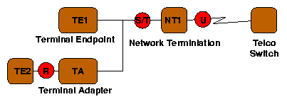
In Europe and Japan, the telco owns the NT-1 and provides the S/T interface to the customer. In North America, however, largely due to the U.S government's unwillingness to allow telephone companies to own customer premises equipment (such as the NT-1), the U interface is provided to the customer, who owns the NT-1. This effectively produces two incompatible varients of ISDN, which some manufacturers have attempted to remedy with devices (such as the Cisco 760) containing both S/T and U jacks.
Normal ISDN devices plug into the S/T interface, an RJ-45 jack carrying two pairs of wires, each pair a current loop. As current flows into the positive line, it flows out of the negative line, maintaining a net balance between the two. The two lines should be grouped together on a single twisted pair, minimizing crosstalk between signals. One pair carries signal from the TE to the NT (user to network), the other pair carries signal from the NT to the TE (network to user).
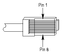
| pin 3 | TE->NT + |
| pin 4 | NT->TE + |
| pin 5 | NT->TE - |
| pin 6 | TE->NT - |
The signals transmitted over the pairs are 192 kbps digital, using an Alternate Mark Inversion (AMI) scheme. Under AMI, one binary value (1) is indicated with no signal, while the other binary value (0) is indicated with either positive or negative signal, in alternating order. Thus, binary 00110101 would be signaled as +-00+0-0. The use of AMI ensures there will be no net DC signal, an important consideration since DC voltages won't be transferred by coupling transformers.
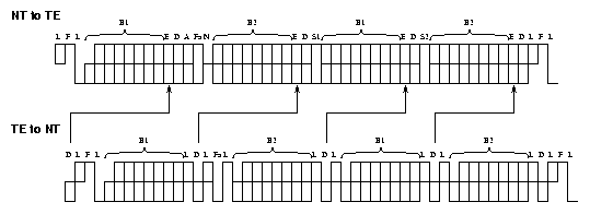
ISDN uses a 48 bit frame, transmitted 4000 times every second (once every 250 microseconds). Each frame includes several L (balancing) bits, which insert an extra positive signal if needed to DC balance the entire frame. A very similar (but not identical) frame format is used on the two pairs, with the TE to NT (user to network) signal synchronized with the NT to TE signal, delayed two bit times. The beginning of each frame is marked with an F (framing) bit, followed by a L (balancing) bit, both reversed polarity. This AMI violation provides a clear frame marker, but since two bits are both reversed, net DC balance is still maintained. In both directions, each frame contains two 8-bit B1 channel slots and two 8-bit B2 channel slots, for a net data rate of 8 bits/slot * 2 slots/frame * 4000 frames/second = 64 kbps on each B channel. Each frame also contains four bits of D channel data, for a net D channel data rate of 4 bits * 4000 frames/second = 16 kbps. In the NT->TE direction four E (echo) bits copy back the D bits from the other direction, providing collision detection for multiple devices competing for the D channel. An 8 kbps S channel (two bits per frame; not currently used) and an A (activation) bit complete the frame structure.
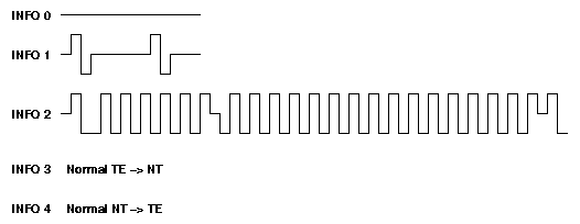
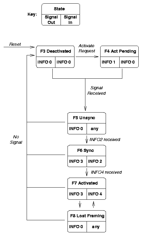
An ISDN TE goes through several states before becoming synchronized. The state diagram makes use of several signals, illustrated below. INFO 0 means no signal. INFO 1 is an unsynchronized signal sent from the TE to the network. INFO 2 is normal ISDN framing (NT to TE) with the B, D, E, and A bits all zero (others normal). INFO 3 is normal ISDN framing (TE to NT), carrying data and synchronized to INFO 2/4. INFO 4 is normal ISDN framing (NT to TE), carrying data with the A bit one. These signals can be observed easily with an oscilloscope; the only difficulty being synchronizing the scope to observe INFO 2, 3 and 4. A signal generator sending a 4 kHz square wave to the scope's trigger will due in a pinch.
An ISDN circuit can be activated by either side of the link. TE requests activation by entering state F4 and transmitting INFO 1. NT requests activation by transmitting INFO 2, causing TE to enter state F5 (upon receiving signal) and then F6 (upon synchronizing with the framing bits). F7 is the normal data carrying state of an ISDN TE. These states have nothing to due with call setup or other operations over the B and D channels, though the TE physical layer must be in state F7 before any higher layer protocols can function.
Q.921 Protocol Overview
Q.921, also referred to as LAPD (Link Access Protocol - D Channel) and a close cousin of HDLC, is the Data Link protocol used over ISDN's D channel.
Frame Format
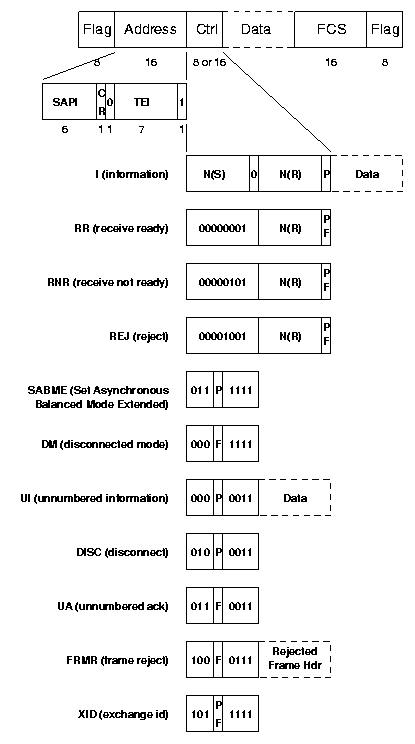
Flag, bit stuffing, and FCS computation are identical to HDLC.
The 16 bits of address contain a command/response (C/R) field, a SAPI (Service Access Point Identifier) and a TEI (Terminal Endpoint Identifier). TEIs are used to distinguish between several different devices using the same ISDN links. TEI 127 is broadcast; other TEI values are dynamically assigned (see below). SAPIs play the role of a protocol or port number, and identify the higher layer protocol being used in the data field. Q.931 messages are sent using SAPI 0, SAPI 16 means X.25, and SAPI 63 is used for TEI assignment procedures. This are usually the only SAPI values used.
Data transfer can occur in one of two formats: Information (I) frames or Unnumbered Information (UI) frames. UI, offering unreliable delivery, is the simplest of the two, since no sequence numbering, acknowledgements, or retransmissions are involved. I frames are numbered modulo 128; the frame number is included in the N(S) field. Acknowledgements are sent using the N(R) field, either piggybacked onto an I frame in the reverse direction, or sent explicitly in an RR or RNR frame. RR indicates that the receiver is ready for more data, RNR indicates a busy condition and places the circuit on hold awaiting a future RR. REJ is a negative acknowledgement, requesting retransmission beginning with frame N(R).
Before I frames can be transferred, a SABME command initializes the sequence numbers to all zeros. The DISC command terminates multi frame operation. Both SABME and DISC are acknowledged with a UA.
Protocol errors (undefined control field; incorrect length frame; invalid acknowledgement; etc) are reported by sending a FRMR with the initial fields of the erroneous frame.
TEI Management
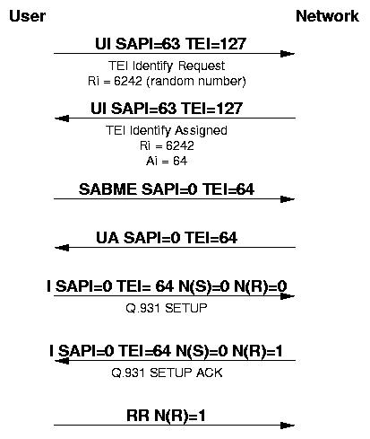
Before any higher level (Q.931) functions can be performed, each ISDN device must be assigned at least one unique TEI value. These numbers can be preassigned (TEIs 0-63), or dynamically assigned (TEIs 64-126). Most TEI assignment is done dynamically, using the TEI management protocol. The user broadcasts an Identity request and the network responds with an Identity assigned containing the TEI value. Functions are also provided to verify and release TEI assignments.
All TEI management functions are performed using TEI 127 (broadcast), SAPI 63, and the following 5-byte UI frame:
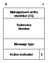
The reference number is a randomly generated 16 bit value used to distinguish between different ISDN devices that might simultaneously request TEI assignment.
The possible message types are:
| Message | Direction | Action indicator |
|---|---|---|
| Identity request (1) | user->network | 127 |
| Identity assigned (2) | network->user | Assigned TEI |
| Identity denied (3) | network->user | |
| Identity check (4) | user->network | TEI to be checked |
| Identity check response (5) | network->user | TEI value(s) in use |
| Identity remove (6) | user->network | TEI to be removed |
| Identity verify (7) | user->network | TEI to be checked |
Sample Exchange
Q.931 Protocol Overview
Q.931 is ISDN's connection control protocol, roughly comparable to TCP in the Internet protocol stack. Q.931 doesn't provide flow control or perform retransmission, since the underlying layers are assumed to be reliable and the circuit-oriented nature of ISDN allocates bandwidth in fixed increments of 64 kbps. Q.931 does manage connection setup and breakdown. Like TCP, Q.931 documents both the protocol itself and a protocol state machine.
-
Note: In accordance with the conventions of ITU standards,
bits are numbered from LSB to MSB, 1 to 8 (Internet standards use
MSB to LSB, 0 to 7).
The general format of a Q.931 message includes a single byte protocol discriminator (8 for Q.931 messages), a call reference value to distinguish between different calls being managed over the same D channel, a message type, and various information elements (IEs) as required by the message type in question:
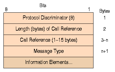
The most important messages types are:
- ALERTING (1)
-
IEs: Bearer capability, Channel identification, Progress indicator,
Display, Signal, High layer compatibility
Direction: Called user -> network -> calling user
The called user is being alerted, i.e "the phone is ringing".
- CALL PROCEEDING (2)
-
IEs: Bearer capability, Channel identification, Progress indicator,
Display, High layer compatibility
Direction: Called user -> network -> calling user
Call establishment is proceeding.
- CONNECT (7)
-
IEs: Bearer capability, Channel identification, Progress indicator,
Display, Date/time, Signal, Low layer compatibility, High layer compatibility
Direction: Called user -> network -> calling user
The call has gone through and been accepted.
- CONNECT ACKNOWLEDGE (15)
-
IEs: Display, Signal
Direction: Calling user -> network -> called user
- SETUP (5)
-
IEs: Sending complete, Repeat indicator, Bearer capability,
Channel identification, Progress indicator, Network specific facilities,
Display, Keypad facility, Signal,
Calling party number, Calling party subaddress,
Called party number, Called party subaddress,
Transit network selection, Repeat indicator,
Low layer compatibility, High layer compatibility
Direction: Calling user -> network -> called user
Initial message sent to initiate a call
- SETUP ACKNOWLEDGE (13)
-
IEs: Channel identification, Progress indicator, Display, Signal
Direction: Called user -> network -> calling user
- SUSPEND (37)
-
IEs: Call identity
Direction: User -> network
ISDN calls can be suspended (put on hold) to allow another call to use the B channel. SUSPEND/RESUME messages manage suspended calls.
- SUSPEND ACKNOWLEDGE (45)
-
IEs: Display
Direction: Network -> user
- SUSPEND REJECT (33)
-
IEs: Cause, Display
Direction: Network -> user
- RESUME (40)
-
IEs: Call identity
Direction: User -> network
- RESUME ACKNOWLEDGE (48)
-
IEs: Channel identification, Display
Direction: Network -> user
- RESUME REJECT (34)
-
IEs: Cause, Display
Direction: Network -> user
- DISCONNECT (69)
-
IEs: Cause, Progress indicator, Display, Signal
A message sent from the user to request call breakdown, or from the network to indicate the call has been cleared.
- RELEASE (77)
-
IEs: Cause, Display, Signal
A message sent to indicate the channel is being released.
- RELEASE COMPLETE (90)
-
IEs: Cause, Display, Signal
- STATUS ENQUIRY (117)
-
IEs: Display
Direction: User -> network
Requests a STATUS message from the network
- STATUS (125)
-
IEs: Cause, Call State, Display
Direction: Network -> user
Indicates current call state in terms of Q.931 state machine
A simple Q.931 message exchange might go as follows:
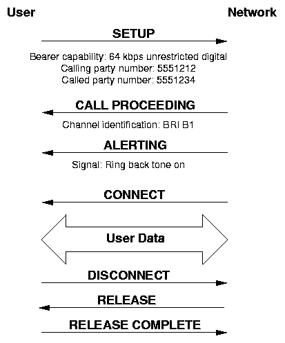
After the Q.931 header, identifying the call and the message type, comes the information elements. There are two types of IEs: single byte and multi-byte, distinguished by their high-order bit:
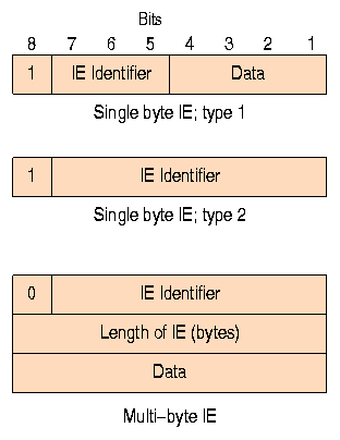
The most important IEs are all multi-byte:
- Bearer capability (4)
-
Specifies a requested service: packet or circuit mode, data rate,
type of information content
- Call identity (16)
-
Used to identify a suspended call
- Call state (20)
-
Describes the current status of a call in terms of the standard
Q.931 state machine
- Called party number (112)
-
The phone number being dialed
- Calling party number (108)
-
The origin phone number
- Cause (16)
-
The reason a call was rejected or disconnected.
A sample of possible cause codes:
1 Unassigned number 3 No route to destination 6 Channel unacceptable 16 Normal call clearing 17 User busy 18 User not responding 19 User alerting; no answer 22 Number changed 27 Destination out of order 28 Invalid number format 34 No circuit/channel available 42 Switching equipment congestion - Channel identification (24)
-
Identify a B channel
- Date/time (41)
-
Poorly defined. Not year 2000 compliant!
- Display (40)
-
Human-readable text. Can be specified with almost
any message to provide text for an LCD display, for example.
- Service Profile Identification (58)
-
Contains a Service Profile Identifier (SPID)
- Signal (52)
-
Provide call status tones according to the following chart:
Meaning North American Practice 0000 0000 Dial tone 350 Hz + 440 Hz; continuous 0000 0001 Ringing 440 Hz + 480 Hz; 2 sec on/4 sec off 0000 0010 Intercept Alternating 440 Hz and 620 Hz; 250 ms each 0000 0011 Network congestion (fast busy) 480 Hz + 620 Hz; 250 ms on/250 ms off 0000 0100 Busy 480 Hz + 620 Hz; 500 ms on/500 ms off 0000 0101 Confirm 350 Hz + 440 Hz; repeated three times: 100 ms on/100 ms off 0000 0110 Answer not used 0000 0111 Call waiting 440 Hz; 300 ms burst 0000 1000 Off-hook warning 1400 Hz + 2060 Hz + 2450 Hz + 2600 Hz; 100 ms on/100 ms off 0011 1111 Tones off
G.711 Protocol
G.711 is the international standard for encoding telephone audio on an 64 kbps channel. It is a pulse code modulation (PCM) scheme operating at a 8 kHz sample rate, with 8 bits per sample. According to the Nyquist theorem, which states that a signal must be sampled at twice its highest frequency component, G.711 can encode frequencies between 0 and 4 kHz. Telcos can select between two different varients of G.711: A-law and mu-law. A-law is the standard for international circuits.
Each of these encoding schemes is designed in a roughly logarithmic fashion. Lower signal values are encoded using more bits; higher signal values require fewer bits. This ensures that low amplitude signals will be well represented, while maintaining enough range to encode high amplitudes.
The actual encoding doesn't use logarithmic functions, however. The input range is broken into segments, each segment using a different interval between decision values. Most segments contain 16 intervals, and the interval size doubles from segment to segment. The illustration shows three segments with four intervals in each.
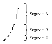
Both encodings are symmetrical around zero. mu-law uses 8 segments of 16 intervals each in each of the positive and negative directions, starting with a interval size of 2 in segment 1, and increasing to an interval size of 256 in segment 8. A-law uses 7 segments. The smallest segment, using an interval of 2, is twice the size of the others (32 intervals). The remaining six segments are "normal", with 16 intervals each, increasing up to an interval size of 128 in segment 7. Thus, A-law is skewed towards representing smaller signals with greater fidelity.