Netopia xDSL Setup
- Configuration Overview
- Public IP Configuration
- Address Translation Configuration
- Disabling RIP
- Enabling Secondary Ethernet Subnets
- Troubleshooting Connectivity Problems
- Resetting to Factory Defaults
Configuration Overview
The Netopia series of routers offer a simple method of router configuration through the use of a GUI menu based interface. Below are screen shots that a user would see if they were either telnetted or consoled into the Netopia router. This router interface is the same for both varieties of DSL routers (7100 and 7200) as well as very similar to the ISDN router interface(3100 and 655).
The interface uses the arrow keys, the tab key, and the enter key to move around and change options. Use the comments of the bottom of the screen to help you know which keys to hit to modify any of the menu options.
Public IP Configuration
In order to configure the Netopia router for public IP addresses, you will need to know a few pieces of information:
- The WAN IP Address
- The WAN IP Subnet Mask
- The Ethernet IP Address
- The Ethernet Subnet Mask
- The router's default gateway
- The DLCI number to be assigned to the router
Once you have this information, you can proceed to set up the router using the screen shots below as a reference guide.
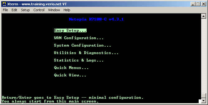
When you log into the Netopia router, you will be presented with a menu screen offering you several choices. Choose the Easy Setup option to begin configuring the Netopia xDSL router.
The first screen allows you to set the Data Link layer encapsulation for the xDSL line. In most cases, you will choose Frame Relay as the majority of lines using the Netopia use this type of connection. If the connection is bridged, then you can choose ATM FUNI instead of Frame Relay for the encapsulation type.
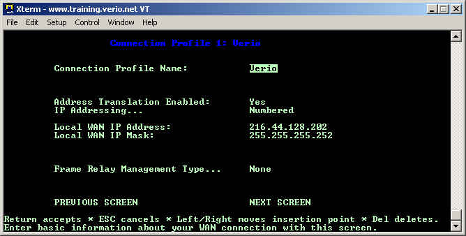
The first blank on this screen is simply a friendly name for this connection. When using NAT, you should enable Address Translation by choosing Yes for its option. Next, you must chooose Number IP addressing for this connection as the customer is being assigned a static WAN IP address which is different from the LAN IP's. Place the customer's WAN IP and WAN IP Subnet Mask in the Local WAN IP Address: and Local WAN IP Mask: blanks. Finally, the Frame Relay Management Type... should be set to None as this is not a true Frame Relay line.
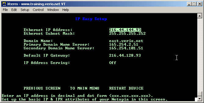
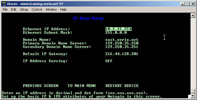
Set the customer's Ethernet IP Address and Subnet mask into the Ethernet IP Address: and Ethernet Subnet Mask: blanks. The Domain Name has no affect on the customer's ability to browse the Internet. If the customer is using DHCP, then this information (Name Servers and Domain Suffix) is given to the customer's computer as a domain suffix for hosts that are not fully qualified. The two name servers are used with DHCP and also allow the router to be able to ping and traceroute by name. The default gateway for the router should be placed in the Default IP Gateway:. Finally, IP Address Serving: is used to enable and disable the DHCP server on the router.
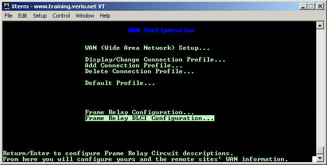
From the Main Menu screen, choose WAN Configuration and move your cursor down to the Frame Relay DLCI Configuration... option as shown below.
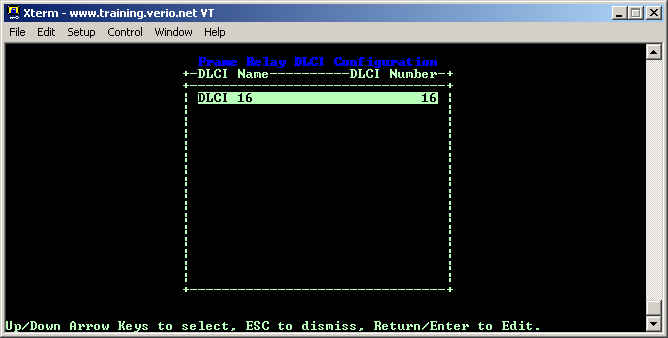
Choose Display/Change DLCIs... from the menu.
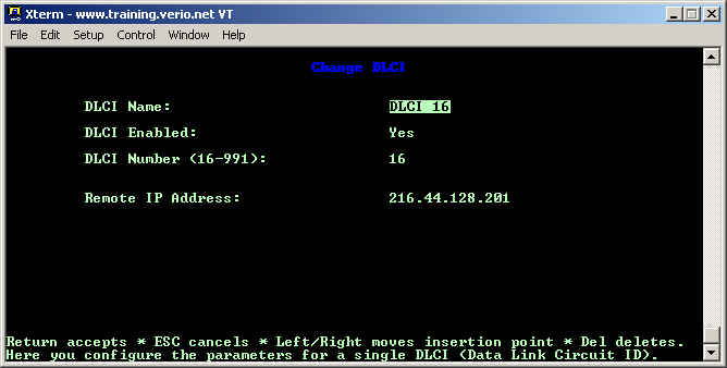
You should have one DLCI listed here, DLCI 16, which will need to be modified before the customer can route.
By default, the Remote IP Address: will be set to 0.0.0.0 as the Netopia router will attempt to use inverse ARP to detect the IP address of the remote router. With the version of firmware that is used on the DSLAM's, this option no longer works, so you must tell the router what the IP address of the Verio router is. Make sure that this IP address is within the subnet mask for the WAN ip address.
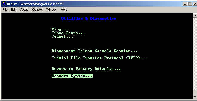
At this stage, the router is configured and only requires a reboot in order for the connection to come up. Choose Restart System... under the Utilities & Diagnostics menu option from the main menu.
Address Translation Configuration
In order to configure the Netopia router for private IP addresses, you will need to know a few pieces of information:
- The WAN IP Address
- The WAN IP Subnet Mask
- The router's default gateway
- The DLCI number to be assigned to the router
Once you have this information, you can proceed to set up the router using the screen shots below as a reference guide.
When you log into the Netopia router, you will be present with a menu screen offering you several choices. Choose the Easy Setup option to begin configuring the Netopia xDSL router.
The first screen allows you to set the Data Link layer encapsulation for the xDSL line. In most cases, you will choose Frame Relay as that is the encapsulation that Northpoint runs on its DSL lines.
The first blank on this screen is simply a friendly name for this connection. When using NAT, you should enable Address Translation by choosing Yes for its option. Next, you must chooose Number IP addressing for this connection as the customer is being assigned a static WAN IP address which is different from the LAN IP's. Place the customer's WAN IP and WAN IP Subnet Mask in the Local WAN IP Address: and Local WAN IP Mask: blanks. Finally, the Frame Relay Management Type... should be set to None as this is not a true Frame Relay line.
Set the customer's Ethernet IP Address and Subnet mask into the Ethernet IP Address: and Ethernet Subnet Mask: blanks. The Domain Name has no affect on the customer's ability to browse the Internet. If the customer is using DHCP, then this information (Name Servers and Search Domain) is given to the customer's computer as a domain suffix for hosts that are not fully qualified. The two name servers are used with DHCP and also allow the router to be able to ping and traceroute by name. The default gateway for the router should be placed in the Default IP Gateway:. Finally, IP Address Serving: is used to enable and disable the DHCP server on the router.
From the Main Menu screen, choose WAN Configuration and move your cursor down to the Frame Relay DLCI Configuration... option as shown below.
Choose Display/Change DLCIs... from the menu.
You should have one DLCI listed here, DLCI 16, which will need to be modified before the customer can route.
By default, the Remote IP Address: will be set to 0.0.0.0 as the Netopia router will attempt to use inverse ARP to detect the IP address of the remote router. With the version of firmware that is used on the DSLAM's, this option no longer works, so you must tell the router what the IP address of the Verio router is. Make sure that this IP address is within the subnet mask for the WAN ip address.
At this stage, the router is configured and only requires a reboot in order for the connection to come up. Choose Restart System... under the Utilities & Diagnostics menu option from the main menu.
NetopiaR7100-Restart.jpg">
Disabling RIP
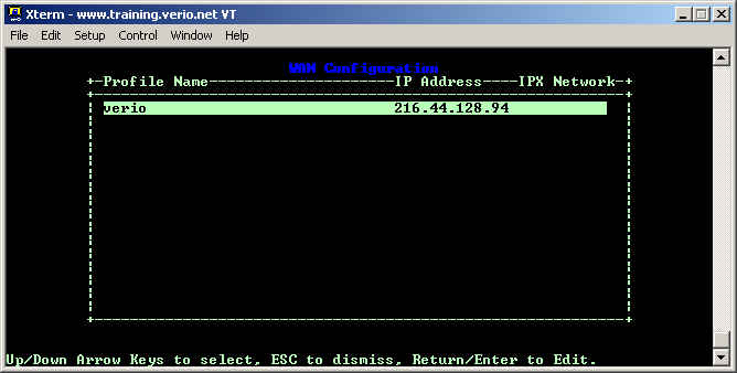
By default, a Netopia router comes with RIP enabled. RIP will sometimes cause problems with intermittant and sporadic routing, so it is often advisable to disabled it. RIP must be disabled in two separate places on the Netopia router, so these screen shots will walk you through doing that. Begin, by connecting to the customer's router and go into the WAN Configuration and you will see a screen like the next one. Choose Display/Change Connection Profile... from the menu.
Generally, a router will only have one connection profile in it that was configured from the Easy Setup menu. In this example, the profile name is verio. Move your cursor to the appropriate connection and press enter.
You will be presented with a screen that displays some more advanced information than was available in the Easy Setup screen. Move your cursor down using the arrow keys to IP Profile Parameters... and press enter.
Make sure that Receive RIP: and Transmit RIP: are both set to off. You can use the enter key to be given a choice for these options.
RIP must also be disabled in the Network Protocols Setup... screen before it is fully disabled. Go back to the Main Menu and choose System Configuration and you will you will see a screen like this. Choose Network Protocols Setup... from this screen by pressing enter.
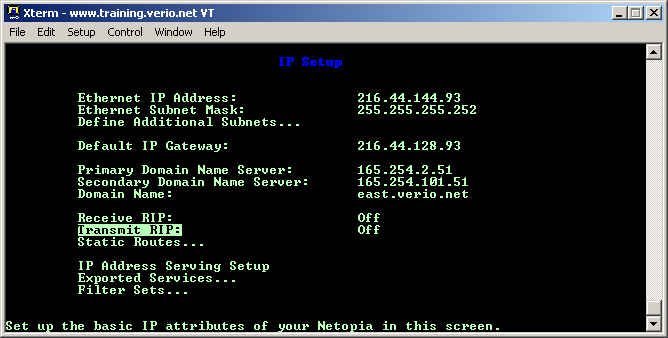
Choose IP Setup... from this screen unless you really are going to configure IPX.
Finally, on this screen, make sure that Receive RIP: and Transmit RIP: are both set to Off to fully disable RIP.
Enabling Secondary Ethernet Subnets
To enable a secondary, or even a tertiary subnet on a Netopia router, go into the System Configuration menu, choose Network Protocols Setup, and then choose IP Setup... on the next screen. You will then be at the IP Setup screen which looks like the picture below. Choose Define Additional Subnets... from this screen by using the arrow keys and the enter key.
You will then see a screen that will show the customer's first ethernet IP and subnet in row #1. Move your cursor down to row #2 and input the customer's secondary IP address and subnet and then restart the router to make the changes take effect.
Troubleshooting Connectivity Problems
- Power cycle the router
- Verify the status of the router lights. Consult Troubleshooting with Router Lights for information on interpretting the lights.
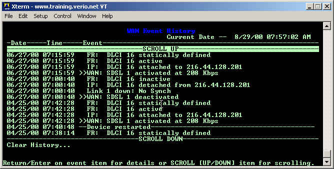
- If the customer can access their router, then can verify the WAN Event History to see the logs of the DSL line's connectivity.
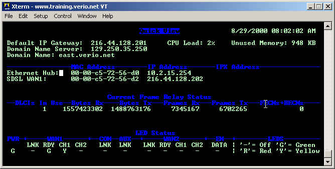
You may also be able to get some useful information from the Quick View screen, such as line errors, and IP addresses that are assigned to the router.
- If the router lights indicate that the line is down, then proceed to open a ticket with the appropriate telephone company or CLEC.
- Since the router is connected to the Internet, the problem is more likely a routing problem. Begin by checking the configuration information within Provo to see if the configuration is sytactically correct as well as has the correct IP information. If any changes are made, you must clear the subscriber on the Redback router and have the customer reboot their router.
- Assuming that the information within Provo is correct, then the problem is more likely than not within the customer's configuration. Verify that the configuration is correct for both the WAN and LAN ip addresses by checking the Easy Setup options listed in this document as appropriate for the type of connection.
- If the line is showing up, Provo has the correct information, and the router appears to be correct, the you are left with a few options. Either the line is having problems, the customer's workstation is misconfigured, or the router is not working correctly. If only one workstation is having problems, then this will be a LAN issue that is beyond our scope of support.
You can have the customer try using the router to try pinging workstations and remote sites on the Internet.
It may be possible that the customer is having routing problems and is only unable to reach certain sites on the Internet. Try using the traceroute utility to reach a few of the sites that customer normally connects to and compare it with the traceroutes that you are seeing from your shell prompt.
- If all else fails, contact your mentor to see where to proceed next. These steps will resolve the majority of your problems but there will still be issues beyond the scope of this document.
Resetting to Factory Defaults
It is important to understand the full ramifications of flashing a router. When a router is reset to factory defaults, all configuration information is lost, so you must have all the needed information before proceeding with this step.
There will be some instances when it is necessary to reset a router back to factory defaults. There are two methods of doing this. If you have the username and password for the router, then you can log into the router, choose Utilities & Diagnostics from the Main Menu, and choose Revert to Factory Defaults... as the picture below demonstrates.
A second method of resetting the router to factory defaults can be used when the username and password for the router is not known. In some models, you can open up the router and press the red reset button near the power supply while the router is powered on. In the newer models, you can insert a paper clip into the slot on the bottom of the router all the way until it hits the bottom. Do this while the router is powered on. When the router lights flash, the router is reset.