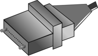
Fiber Optic Connectors
Fiber Optic Connectors have traditionally been the biggest concern in using fiber optic systems. While connectors were once unwieldy and difficult to use, connector manufacturers have standardized and simplified connectors greatly. This increasing user-friendliness has contributed to the increase in the use of fiber optic systems; it has also taken the emphasis off the proper care and handling of optical connectors.
This article covers connector
basics including the parts of a fiber optic connector, installing fiber
optic connectors, and the cleaning and handling of installed connectors.
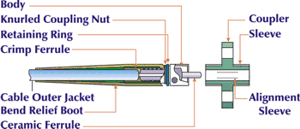
Figure 1 - Parts of a Fiber Optic Connector
|
Fiber-to-fiber interconnection can consist of a splice, a permanent connection, or a connector, which differs from the splice in its ability to be disconnected and reconnected. Fiber optic connector types are as various as the applications for which they were developed. Different connector types have different characteristics, different advantages and disadvantages, and different performance parameters. But all connectors have the same four basic components. |
|
| The Ferrule: |
The fiber is mounted in a long, thin cylinder, the ferrule, which acts as a fiber alignment mechanism. The ferrule is bored through the center at a diameter that is slightly larger than the diameter of the fiber cladding. The end of the fiber is located at the end of the ferrule. Ferrules are typically made of metal or ceramic, but they may also be constructed of plastic. |
| The Connector Body: |
Also called the connector housing, the connector body holds the ferrule. It is usually constructed of metal or plastic and includes one or more assembled pieces which hold the fiber in place. The details of these connector body assemblies vary among connectors, but bonding and/or crimping is commonly used to attach strength members and cable jackets to the connector body. The ferrule extends past the connector body to slip into the coupling device. |
| The Cable: |
The cable is attached to the connector body. It acts as the point of entry for the fiber. Typically, a strain-relief boot is added over the junction between the cable and the connector body, providing extra strength to the junction. |
| The Coupling Device: |
Most fiber optic connectors do not use the male-female configuration common to electronic connectors. Instead, a coupling device such as an alignment sleeve is used to mate the connectors. Similar devices may be installed in fiber optic transmitters and receivers to allow these devices to be mated via a connector. These devices are also known as feed-through bulkhead adapters. |
|
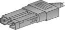
Table 1 illustrates some types of optical connectors and lists some specifications. Each connector type has strong points. For example, ST connectors are a good choice for easy field installations; the FC connector has a floating ferrule that provides good mechanical isolation; the SC connector offers excellent packing density, and its push-pull design resists fiber end face contact damage during unmating and remating cycles. |
|
|
Table 1- Types Of Optical Connectors |
| Connector | Insertion Loss | Repeatability | Fiber Type | Applications |
FC |
0.50-1.00 dB |
>0.20 dB | SM, MM | Datacom, Telecommunications |
 FDDI |
0.20-0.70 dB | 0.20 dB | SM, MM | Fiber Optic Network |
|
|
0.15 db (SM) 0.10 dB (MM) |
0.2 dB | SM, MM | High Density Interconnection |
|
|
0.30-1.00 dB | 0.25 dB | SM, MM | High Density Interconnection |
|
|
0.20-0.45 dB | 0.10 dB | SM, MM | Datacom |
|
|
0.20-0.45 dB | 0.10 dB | SM, MM | Datacom |
|
|
Typ. 0.40 dB (SM) Typ. 0.50 dB (MM) |
Typ. 0.40 dB (SM) Typ. 0.20 dB (MM) |
SM, MM | Inter-/Intra-Building, Security, Navy |