X.25
Introduction
X.25 is an International Telecommunication Union-Telecommunication Standardization Sector (ITU-T) protocol standard for WAN communications that defines how connections between user devices and network devices are established and maintained. X.25 is designed to operate effectively regardless of the type of systems connected to the network. It is typically used in the packet-switched networks (PSNs) of common carriers, such as the telephone companies. Subscribers are charged based on their use of the network. The development of the X.25 standard was initiated by the common carriers in the 1970s. At that time, there was a need for WAN protocols capable of providing connectivity across public data networks (PDNs). X.25 is now administered as an international standard by the ITU-T.
X.25 Devices and Protocol Operation
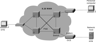
X.25 network devices fall into three general categories: data terminal equipment (DTE), data circuit-terminating equipment (DCE), and packet-switching exchange (PSE). Data terminal equipment devices are end systems that communicate across the X.25 network. They are usually terminals, personal computers, or network hosts, and are located on the premises of individual subscribers. DCE devices are communications devices, such as modems and packet switches, that provide the interface between DTE devices and a PSE, and are generally located in the carrier's facilities. PSEs are switches that compose the bulk of the carrier's network. They transfer data from one DTE device to another through the X.25 PSN. Figure 17-1 illustrates the relationships among the three types of X.25 network devices.
Figure 17-1: DTEs, DCEs, and PSEs Make Up an X.25 Network

Packet Assembler/Disassembler
There used to be an explicit gizmo called the PAD (Packet Assembly and Disassembly) which waited for 128 bytes from the terminal before it sent off a packet, and likewise, broke the packet up at the receiver side to give the illusion of a stream. Nowadays, the PAD's functionality is performed at the DTE. Almost all DTE/DCE interfaces for x.25 are modems.
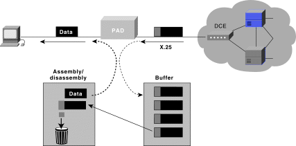
The packet assembler/disassembler (PAD) is a device commonly found in X.25 networks. PADs are used when a DTE device, such as a character-mode terminal, is too simple to implement the full X.25 functionality. The PAD is located between a DTE device and a DCE device, and it performs three primary functions: buffering (storing data until a device is ready to process it), packet assembly, and packet disassembly. The PAD buffers data sent to or from the DTE device. It also assembles outgoing data into packets and forwards them to the DCE device. (This includes adding an X.25 header.) Finally, the PAD disassembles incoming packets before forwarding the data to the DTE. (This includes removing the X.25 header.) Figure 17-2 illustrates the basic operation of the PAD when receiving packets from the X.25 WAN.
Figure 17-2: The PAD Buffers, Assembles, and Disassembles Data Packets

X.25 Session Establishment
X.25 sessions are established when one DTE device contacts another to request a communication session. The DTE device that receives the request can either accept or refuse the connection. If the request is accepted, the two systems begin full-duplex information transfer. Either DTE device can terminate the connection. After the session is terminated, any further communication requires the establishment of a new session.
X.25 Virtual Circuits
A virtual circuit is a logical connection created to ensure reliable communication between two network devices. A virtual circuit denotes the existence of a logical, bidirectional path from one DTE device to another across an X.25 network. Physically, the connection can pass through any number of intermediate nodes, such as DCE devices and PSEs. Multiple virtual circuits (logical connections) can be multiplexed onto a single physical circuit (a physical connection). Virtual circuits are demultiplexed at the remote end, and data is sent to the appropriate destinations. Figure 17-3 illustrates four separate virtual circuits being multiplexed onto a single physical circuit.
Figure 17-3: Virtual Circuits Can Be Multiplexed onto a Single Physical Circuit

Two types of X.25 virtual circuits exist: switched and permanent. Switched virtual circuits (SVCs) are temporary connections used for sporadic data transfers. They require that two DTE devices establish, maintain, and terminate a session each time the devices need to communicate. Permanent virtual circuits (PVCs) are permanently established connections used for frequent and consistent data transfers. PVCs do not require that sessions be established and terminated. Therefore, DTEs can begin transferring data whenever necessary because the session is always active.
The basic operation of an X.25 virtual circuit begins when the source DTE device specifies the virtual circuit to be used (in the packet headers) and then sends the packets to a locally connected DCE device. At this point, the local DCE device examines the packet headers to determine which virtual circuit to use and then sends the packets to the closest PSE in the path of that virtual circuit. PSEs (switches) pass the traffic to the next intermediate node in the path, which may be another switch or the remote DCE device.
When the traffic arrives at the remote DCE device, the packet headers are examined and the destination address is determined. The packets are then sent to the destination DTE device. If communication occurs over an SVC and neither device has additional data to transfer, the virtual circuit is terminated.
The X.25 Protocol Suite
The X.25 protocol suite maps to the lowest three layers of the OSI reference model. The following protocols are typically used in X.25 implementations: Packet-Layer Protocol (PLP), Link Access Procedure, Balanced (LAPB), and those among other physical-layer serial interfaces (such as EIA/TIA-232, EIA/TIA-449, EIA-530, and G.703). Figure 17-4 maps the key X.25 protocols to the layers of the OSI reference model.
Figure 17-4: Key X.25 Protocols Map to the Three Lower Layers of the OSI Reference Model

Packet-Layer Protocol
PLP is the X.25 network layer protocol. PLP manages packet exchanges between DTE devices across virtual circuits. PLPs also can run over Logical Link Control 2 (LLC2) implementations on LANs and over Integrated Services Digital Network (ISDN) interfaces running Link Access Procedure on the D channel (LAPD).
The PLP operates in five distinct modes: call setup, data transfer, idle, call clearing, and restarting.
Call setup mode is used to establish SVCs between DTE devices. A PLP uses the X.121 addressing scheme to set up the virtual circuit. The call setup mode is executed on a per-virtual-circuit basis, which means that one virtual circuit can be in call setup mode while another is in data transfer mode. This mode is used only with SVCs, not with PVCs.
Data transfer mode is used for transferring data between two DTE devices across a virtual circuit. In this mode, PLP handles segmentation and reassembly, bit padding, and error and flow control. This mode is executed on a per-virtual-circuit basis and is used with both PVCs and SVCs.
Idle mode is used when a virtual circuit is established but data transfer is not occurring.
It is executed on a per-virtual-circuit basis and is used only with SVCs.
Call clearing mode is used to end communication sessions between DTE devices and to terminate SVCs. This mode is executed on a per-virtual-circuit basis and is used only with SVCs.
Restarting mode is used to synchronize transmission between a DTE device and a locally connected DCE device. This mode is not executed on a per-virtual-circuit basis. It affects all the DTE device's established virtual circuits.
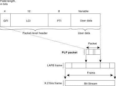
Four types of PLP packet fields exist:
- General Format Identifier (GFI)—Identifies packet parameters, such as whether the packet carries user data or control information, what kind of windowing is being used, and whether delivery confirmation is required.
- Logical Channel Identifier (LCI)—Identifies the virtual circuit across the local DTE/DCE interface.
- Packet Type Identifier (PTI)—Identifies the packet as one of 17 different PLP packet types.
- User Data—Contains encapsulated upper-layer information. This field is present only in data packets. Otherwise, additional fields containing control information are added.
Link Access Procedure, Balanced
LAPB is a data link layer protocol that manages communication and packet framing between DTE and DCE devices. LAPB is a bit-oriented protocol that ensures that frames are correctly ordered and error-free.
Three types of LAPB frames exist: information, supervisory, and unnumbered. The information frame (I-frame) carries upper-layer information and some control information. I-frame functions include sequencing, flow control, and error detection and recovery. I-frames carry send- and receive-sequence numbers. The supervisory frame (S-frame) carries control information. S-frame functions include requesting and suspending transmissions, reporting on status, and acknowledging the receipt of I-frames. S-frames carry only receive-sequence numbers. The unnumbered frame (U frame) carries control information. U-frame functions include link setup and disconnection, as well as error reporting. U frames carry no sequence numbers.
The X.21bis Protocol
X.21bis is a physical layer protocol used in X.25 that defines the electrical and mechanical procedures for using the physical medium. X.21bis handles the activation and deactivation of the physical medium connecting DTE and DCE devices. It supports point-to-point connections, speeds up to 19.2 kbps, and synchronous, full-duplex transmission over four-wire media. Figure 17-5 shows the format of the PLP packet and its relationship to the LAPB frame and the X.21bis frame.
Figure 17-5: The PLP Packet Is Encapsulated Within the LAPB Frame and the X.21bis Frame

LAPB Frame Format
LAPB frames include a header, encapsulated data, and a trailer. Figure 17-6 illustrates the format of the LAPB frame and its relationship to the PLP packet and the X.21bis frame.
The following descriptions summarize the fields illustrated in Figure 17-6:
- Flag—Delimits the beginning and end of the LAPB frame. Bit stuffing is used to ensure that the flag pattern does not occur within the body of the frame.
- Address—Indicates whether the frame carries a command or a response.
- Control—Qualifies command and response frames and indicates whether the frame is an I-frame, an S-frame, or a U-frame. In addition, this field contains the frame's sequence number and its function (for example, whether receiver-ready or disconnect). Control frames vary in length depending on the frame type.
- Data—Contains upper-layer data in the form of an encapsulated PLP packet.
- FCS—Handles error checking and ensures the integrity of the transmitted data.
Figure 17-6: An LAPB Frame Includes a Header, a Trailer, and Encapsulated Data

X.121 Address Format
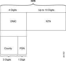
X.121 addresses are used by the X.25 PLP in call setup mode to establish SVCs. Figure
17-7 illustrates the format of an X.121 address.
The X.121 Address field includes the International Data Number (IDN), which consists of two fields: the Data Network Identification Code (DNIC) and the National Terminal Number (NTN).
DNIC is an optional field that identifies the exact PSN in which the destination DTE device is located. This field is sometimes omitted in calls within the same PSN. The DNIC has two subfields: Country and PSN. The Country subfield specifies the country in which the destination PSN is located. The PSN field specifies the exact PSN in which the destination DTE device is located.
The NTN identifies the exact DTE device in the PSN for which a packet is destined. This field varies in length.
Figure 17-7: The X.121 Address Includes an IDN Field
